texte en français / Text in Deutsch
By V.Weissensteiner et C.Trüssel (English translation by Wookey)
With pictures by C.Trüssel
There is a detailled description of the mounting method in Stalactite 41,1,1991.
Take note surveyors! Here’s how it works:

infos/questions: Rolf Siegenthaler or Christian Bieri
Description of the problem
When surveying a cave with a compass,the magnetic error and errors due to the difficulties of sighting the compass on steep legs are the most significant.
Reading the instrument and sighting accurately is not possible just by eye in these cases. The device presented below solves this inconvenience and allows very accurate surveying.
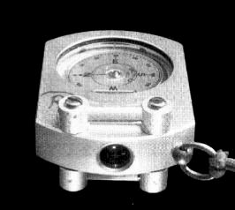
The device relies on the principle of reflection and refraction of light in a glass cylinder. The tests of prototypes, done in 1983 during an expedition in the „Frauenmauer-Langenstein“ cave system were considered a success. The rigid device presented here is far superior to all flexible types. The pictures show installation on a „Suunto“ instrument.
Description of the device

- The axes of the glass bars must be exactly perpendicular to the optical axis of the instrument and at the same time parallel to the horizontal surface of the instrument.
- A gap of 1 to 3 mm must remain free for sighting between the surface of the instrument and the glass bars.
- The length of the bars doesn’t need to be the width of the instrument. A length of 2 to 3 times the diameter of the lens window is fine.
- Using a semi-cylinder is also possible. However, the tests on this gave deceptive results (too little luminosity).
- The glass bars must be sited in the same vertical plane as the instrument lens.
- The best attachment is achieved with screwed supports at the two ends. Fixing with glue doesn’t last long under caving conditions.
- The best material for the cylinders is glass, however plexiglass also gave satisfactory results.
Use
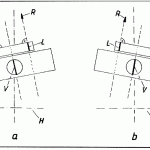
When this mark and the instrument’s sighting mark are aligned (vertically) you can take a correct reading of direction. (Fig. 3a).
Slight rotations of the intrument in the horizontal axis are seen as a deviation of the luminous mark in the bar to the left or to the right of the instrument’s sighting mark. (Fig. 3b and 3c).
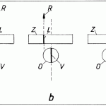
What happens when the instrument is not horizontal? The reading is falsified by the compass card which sticks and rest at an angle.
You can recognise this tilting by the instrument sighting mark and the luminous mark in the glass bar not lining up, and their axes being tilted. (Fig. 2a and 2b). Tilting of the compass card forwards or backwards is recognised by the position of the card in the lens and is largely corrected by the nature of the instrument. To get the best possible illumination of the instrument it should not be lit from the side.
Especially for reading long legs, it is important to use a bright light on the station that lights the instrument accurately. If this isn’t done the luminance in the glass bar will be very vague and difficult to recognise. A single source of light on the sighted point should be found. It is preferable to use a coloured light (orange or green). A precise reading is not possible unless the various possible faults, cited above, are eliminated.
Description of the construction
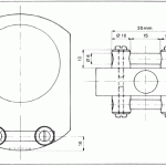
To fit the device it is necessary to work conscientiously and accurately. One good method of mounting is described below, (Fig. 4). The body of the „Suunto“ is made of solid aluminium.. Holes of 2.4mm diameter for the fixing screws go through it without problems after marking and punching. Then these are tapped with an M3 tap on both side as far as the centre of the body.
The 10mm long supports that hold the bars are then made from aluminium bar stock. A hole of 3mm for the (brass or non-magnetic steel) fixing screw is drilled along the axis and another hole of 6mm diameter at a right angle to the first to hold the plexiglass bar. After cutting the bars to 35mm, they are put into the support until the ends are flush with the supports then holes of 3mm drilled through the bar for the fixing screws.
The device that will be attached on top of the compass comprises two supports and a plexiglass bar. The second one, identical to the first, is attached below. Each of the two parts are attached by two falt-head machine screws. When the plexiglass bars are placed exactly at 90° to the axis of the body and parallel to the surface of it, the compass is ready to use.
Alternatively you can modify the construction to simply the mounting. Make two 3mm diameter holes through the compass. The supports of the device which will go on the bottom are tapped with an M3 tap and then the fixing screw goes all the way through the top device and body to screw into the bottom support.
With this small modification the „Suunto“ compass can still be used without problems. Carrying the compass in the cave is no problem and the instrument still fits in the pocket.
For sighting, an actylene light suffices for illumination. For the sighted point (station), it is always best to use an electric light.
The SSS Berne can do the fitting of the device for you!
Bibliographie
The contribution of Volker Weissensteiner is in: „Eine Zusatzeinrichtung für den Flüssigkeitsgedämpften Kompass“, „Die Höhle“ N° 4/ 1989, edited by the Austrian Caving Association.
This article was published in Stalactite, the journal of the Société Suisse de Spéléologie:
WEISSENSTEINER, V. & TRÜSSEL, Cl.
(1991): Ein nützliches Visiersystem für den Kompass. Un dispositif de visée très pratique pour les boussoles. – Stalactite 41 (1): 32-34.